Write-Back Caching and In-Flight Request Handling in SSDs
An in-depth exploration of write-back caching mechanisms in modern SSDs, including the management of in-flight requests, power-loss protection strategies, and architectural considerations that balance performance with data integrity.

1. Introduction and Core Concepts
Solid-State Drives (SSDs) have transformed digital storage by delivering exceptional speed through parallel architectures and the elimination of moving parts. At the heart of their design is a smart caching system that bridges the gap between fast host interfaces and the relatively slower NAND flash storage.
This paper explores the ins and outs of write-back caching and in-flight request handling in modern SSDs, looking at how manufacturers balance performance optimization with data integrity.
1.1 Caching Strategies in SSDs
SSDs use several caching approaches to manage data flow between the host computer and flash storage. Each approach has its own benefits and drawbacks:
Write-back caching stores incoming write operations in fast, temporary memory (usually DRAM) and immediately tells the host that the write is complete. The data is later moved to permanent flash storage in the background.
This method dramatically improves write performance by separating the host operations from the slower flash programming steps. The main advantage is significantly better write speeds, especially for random writes, as the host only experiences the quick DRAM write times rather than waiting for data to be saved to flash.
Write-through caching also uses the cache but doesn’t confirm write completion until the data is safely stored in permanent memory. While this ensures data safety, it misses out on the speed benefits of the write-back approach since the host must wait for the entire process to finish.
Write-around caching skips the cache entirely for writes, sending data directly to permanent storage. This approach works well for sequential workloads where caching offers minimal benefit, or in situations where write speed is less important than read performance, saving cache space for read operations.
1.2 In-Flight Requests: Definition and Implications
In-flight requests are a key concept for understanding SSD operations. These are commands that the SSD has accepted and acknowledged to the host but hasn’t yet permanently saved to flash storage. These requests exist temporarily in the SSD’s volatile memory and could be lost if power suddenly fails.
The existence of in-flight requests creates a fundamental design challenge: how to balance the speed benefits of immediate acknowledgment against the risk of data loss. This challenge is especially important in business environments where data integrity is critical.
In-flight requests affect several aspects of SSD operation:
Data Consistency: The gap between acknowledgment and permanent storage creates a window where confirmed data might be lost.
Recovery Complexity: After unexpected power loss, the SSD must figure out which operations were completed and which were in progress when power failed.
Performance Scaling: Higher performance often means more in-flight requests, making power-loss protection more complicated.
Resource Allocation: Managing in-flight requests requires smart buffer allocation strategies and affects controller design.
2. Architectural Overview of SSD Write-Back Caching
2.1 End-to-End Request Flow
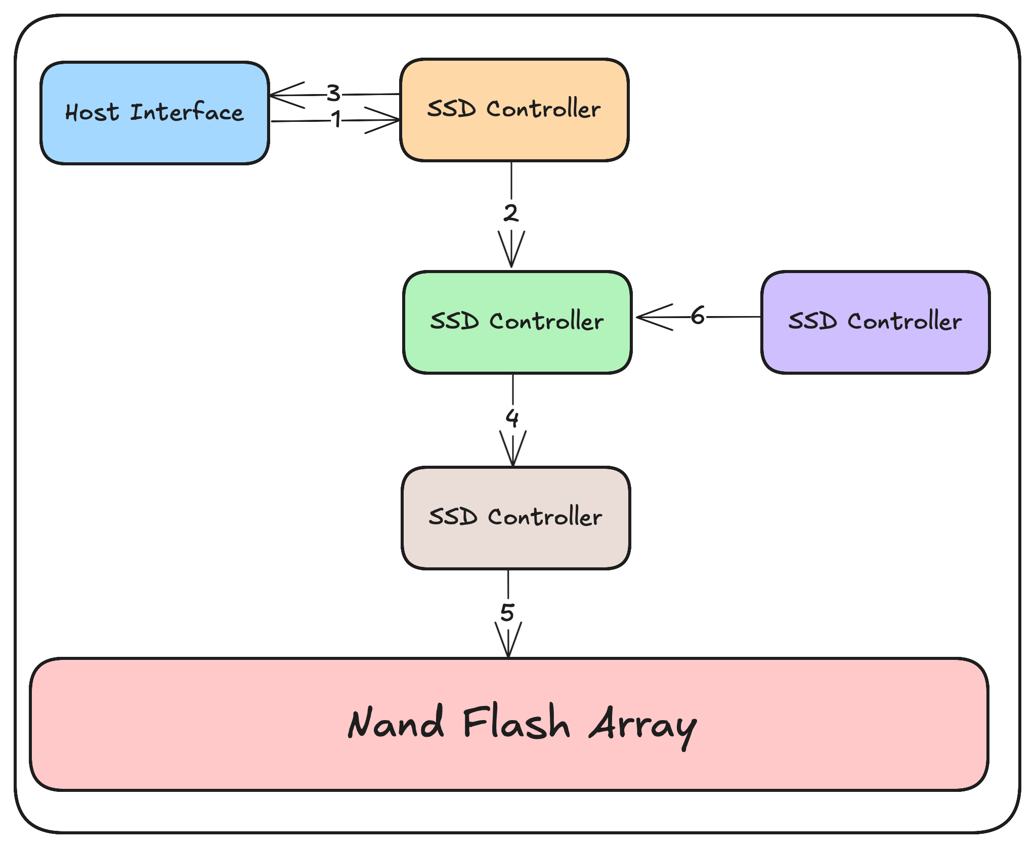
To fully understand SSD write operations, we need to examine the complete path from host interface to flash storage:
Host Command Processing: The host sends write commands through the SSD interface (NVMe, SATA, SAS), which are received by the SSD controller. These commands include addresses, data, and command parameters.
Write Data Ingestion: Data transfers from the host into the SSD’s DRAM cache. Modern enterprise SSDs typically have 1-4GB of DRAM cache per TB of storage, allowing them to handle high-speed write operations.
Write Acknowledgment: Once the data is successfully transferred to DRAM, the controller sends a completion signal to the host, freeing it to continue with other tasks. At this point, data exists only in temporary memory and becomes an in-flight request.
- Request Queuing and Scheduling: In-flight write requests are organized in queues, where they undergo various optimizations including:
- Combining adjacent or overlapping writes
- Distributing writes evenly across the drive (wear-leveling)
- Flash-specific optimizations (like aligning to page boundaries)
- Flash Translation Layer (FTL) Processing: The logical addresses from the host are mapped to physical locations in the flash memory. This layer performs important functions including:
- Converting logical addresses to physical locations
- Managing garbage collection
- Handling bad blocks
- Distributing writes to extend drive life
- NAND Programming Operations: Data moves from the DRAM cache to the flash memory. This stage is when data is actually permanently saved and typically involves:
- Sending commands to the flash chips
- Transferring data to NAND page buffers
- Program operations that physically change the flash cells
- Verifying that data was written correctly
- Cache Eviction: Once data has been successfully saved to flash, the corresponding cache entries can be removed, making room for new incoming data.
2.2 Role of the SSD Controller
The SSD controller orchestrates the entire caching process using sophisticated algorithms to manage data flow. Key controller responsibilities include:
Queue Management: Maintaining ordered lists of pending operations while optimizing for flash characteristics.
Resource Allocation: Dynamically assigning DRAM cache space between read and write operations based on current workload.
Scheduling: Determining the best order of operations to maximize throughput and minimize unnecessary writes.
Power-Loss Monitoring: Continuously checking power conditions and initiating protective measures when problems are detected.
Error Detection and Correction: Implementing error correction algorithms to ensure data integrity throughout the caching and storage process.
The controller’s firmware implements sophisticated state tracking that monitors the status of each in-flight request, ensuring that all operations are either completed or properly recovered if interrupted.
3. Power-Loss Protection Mechanisms
3.1 The Power-Loss Vulnerability Window
Write-back caching creates a vulnerability window where acknowledged data exists only in temporary memory. Modern enterprise SSDs use sophisticated power-loss protection (PLP) mechanisms to address this vulnerability, typically consisting of:
Energy Storage Devices: Supercapacitors or tantalum capacitors that can provide enough power to complete critical operations during power loss.
Power Monitoring Circuits: Specialized circuits that detect power problems within microseconds, triggering emergency procedures before voltage drops too low.
Flush Prioritization Logic: Algorithms that determine the best order for saving cached data during power emergencies, prioritizing based on factors such as data importance and energy efficiency.
3.2 Supercapacitor-Based Protection
Enterprise SSDs often use supercapacitors as the main energy source for power-loss protection. These components offer several advantages:
Energy Density: Modern supercapacitors provide enough energy to save multiple gigabytes of cached data.
Long Service Life: Quality supercapacitors maintain their capacity through hundreds of thousands of charge/discharge cycles.
Temperature Stability: Advanced supercapacitors work effectively across the wide temperature ranges found in data centers.
The relationship between supercapacitor capacity, cache size, and performance follows an important equation:
Minimum Energy = (Cache Size × Write Power) × (Flush Time + Safety Margin)
Where:
- Minimum Energy is the least amount of energy required
- Write Power is how much power is used during write operations
- Flush Time is how long it takes to transfer cached data to flash
- Safety Margin accounts for component aging and unexpected conditions
3.3 Flush Procedures During Power Loss
When power loss is detected, the SSD begins a carefully orchestrated sequence of operations:
Emergency Detection: Power monitoring circuits detect voltage drops below preset thresholds, typically triggering at 10-15% below normal voltage.
Non-Essential Function Termination: The controller immediately stops all non-critical operations, including processing new commands and background tasks.
Cache State Preservation: Critical information describing the cache state is immediately saved to permanent memory.
Prioritized Data Flushing: In-flight write data moves from DRAM to flash in an order determined by flush prioritization algorithms.
Verification and Finalization: Final checks ensure that all critical data has been successfully saved.
The entire procedure typically finishes within milliseconds, limited mainly by the flash programming time rather than the data transfer speed.
4. Cache Management and Optimization
4.1 Write Coalescing and Command Merging
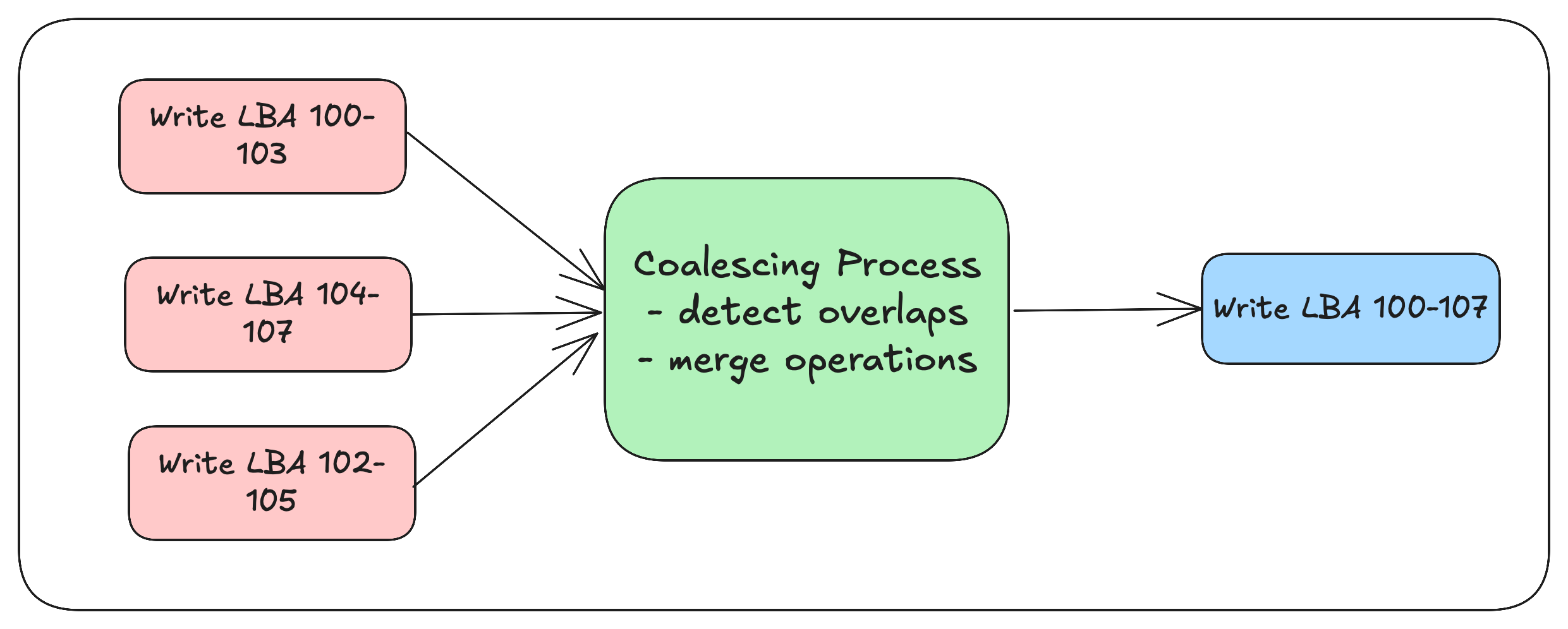
Write coalescing is a fundamental optimization technique in SSD caching. It combines multiple write operations targeting nearby or overlapping addresses into unified operations before saving them to flash.
This strategy provides several benefits:
Reduced Write Amplification: By consolidating partial page writes into full page writes, the SSD reduces the overhead of read-modify-write operations.
Extended Flash Lifespan: Fewer program/erase cycles directly translate to longer flash lifetime.
Improved Performance: Consolidated writes make more efficient use of the SSD’s internal parallel architecture.
Advanced SSDs implement multi-level coalescing at both the logical level (combining operations targeting the same address) and the physical level (aligning writes to flash page boundaries).
4.2 Cache Partitioning Strategies
Modern SSDs employ sophisticated cache partitioning techniques to optimize performance across different workloads:
Static Partitioning: Dedicating fixed portions of cache to specific functions such as read caching, write buffering, and metadata storage.
Dynamic Partitioning: Adjusting cache allocation in real-time based on workload characteristics and queue depths.
Workload-Aware Partitioning: Using machine learning algorithms to predict access patterns and optimize cache allocation proactively.
Enterprise SSDs often implement hybrid approaches, combining static guarantees for critical functions with dynamic allocation for adaptability.
4.3 Eviction Algorithms
Cache eviction policies determine which data stays in the limited DRAM cache and which is removed to make room for new entries. Common algorithms include:
Least Recently Used (LRU): Removes data that hasn’t been accessed for the longest time, optimizing for temporal locality.
First-In-First-Out (FIFO): Implements a straightforward queue structure, removing the oldest cached entries first.
Adaptive Replacement Cache (ARC): Balances recency and frequency considerations by maintaining multiple lists and dynamically adjusting allocation between them.
Cost-Aware Eviction: Considers the computational and energy cost of regenerating cached data when making eviction decisions.
Enterprise SSDs typically implement variations of these algorithms, often considering additional factors such as write amplification impact and flash wear implications.
5. Hardware Integration
5.1 DRAM Subsystem Design
The DRAM subsystem serves as the main cache repository and is a critical component in the write-back caching architecture. Design considerations include:
Interface Selection: High-speed interfaces such as DDR4 or LPDDR4x that provide enough bandwidth to match both host and flash interfaces.
Error Protection: Implementation of error correction code (ECC) or more sophisticated error correction techniques to ensure data integrity within the volatile cache.
Power Domain Isolation: Careful separation of power domains to enable clean shutdown during power emergencies.
Thermal Considerations: Management of DRAM heat characteristics, particularly in high-performance environments with sustained write workloads.
Leading enterprise SSDs use custom DRAM controllers that optimize specifically for caching use cases rather than general-purpose memory access patterns.
5.2 Controller Architecture and Firmware Design
The SSD controller implements the logic governing the caching mechanism, with architecture typically featuring:
Multi-Core Processing: Modern controllers use multiple ARM or custom processor cores to handle the complex parallelism required.
Hardware Acceleration: Dedicated engines for common operations such as error correction calculation, encryption, and compression.
State Management Hardware: Specialized circuits for tracking the status of in-flight requests across power cycles.
Interface Bridges: High-speed connections between host interfaces, cache memory, and flash channels.
Firmware design for cache management requires careful attention to state preservation, implementing transactional models that ensure consistency across power cycles and unexpected interruptions.
5.3 Power-Loss Protection Circuits
The integration of power-loss protection adds extra hardware complexity:
Voltage Monitoring: Precision circuits that can detect voltage problems with sub-microsecond response times.
Energy Storage Management: Smart charging circuits that keep supercapacitors at optimal charge levels while monitoring health parameters.
Emergency Power Routing: Specialized power paths that activate during emergencies, isolating critical components from failing system power.
Temperature Compensation: Circuits that adjust behavior based on temperature conditions, as supercapacitor performance varies with temperature.
The integration of these components requires careful attention to signal integrity, thermal design, and electromagnetic compatibility considerations.
6. State-of-the-Art Systems
6.1 Enterprise SSD Implementations
Today’s enterprise SSDs showcase diverse approaches to write-back caching:
Samsung PM1733 Series implements a tiered caching system with multiple levels of temporary and permanent cache. This architecture uses machine learning algorithms to predict access patterns and dynamically adjust caching policies. The PM1733’s power-loss protection system uses tantalum capacitors instead of supercapacitors, offering better temperature stability at the cost of somewhat lower energy density.
Intel Optane SSDs incorporate 3D XPoint memory as both primary storage and an intermediate cache tier. This architecture blurs the traditional boundaries between cache and storage, implementing a continuous performance gradient rather than distinct tiers. The reduced write latency of 3D XPoint significantly narrows the performance gap between cache and storage, allowing for smaller volatile cache sizes and correspondingly reduced power-loss protection requirements.
Micron 7450 NVMe SSDs feature a distributed cache architecture where cache functionality is spread across multiple controller cores, each managing a dedicated segment of the overall cache. This approach enhances parallelism and reduces contention but introduces additional complexity in cache coherence mechanisms. The 7450 series implements adaptive write coalescing that changes its behavior based on detected workload patterns.
6.2 Performance and Reliability Tradeoffs
Enterprise SSD manufacturers make distinctive design choices reflecting different priorities:
Cache Size vs. Power-Loss Protection: Larger caches deliver better performance but require more extensive power-loss protection mechanisms. Manufacturers balance these factors differently based on target use cases.
Write Performance vs. Endurance: Aggressive write coalescing improves endurance but may introduce latency. Different products position themselves along this spectrum according to market positioning.
Consistency vs. Peak Performance: Some designs prioritize consistent performance under all conditions, while others optimize for maximum throughput under ideal circumstances.
These tradeoffs appear in product specifications, with some manufacturers emphasizing sustained performance while others highlight peak performance figures.
7. Future Directions
7.1 Emerging Technologies and Approaches
Several technological developments are reshaping SSD caching strategies:
Computational Storage: Adding processing capabilities directly into storage devices enables more sophisticated caching algorithms and reduces the amount of data movement.
Machine Learning-Based Prefetching: Advanced predictive models anticipate future access patterns with increasing accuracy, enabling proactive cache loading.
Storage Class Memory (SCM) Integration: Technologies like 3D XPoint and FeRAM are creating intermediate tiers between DRAM and NAND, offering new architectural possibilities.
Zoned Namespaces (ZNS): By exposing the zone-based nature of underlying NAND, ZNS enables more efficient cache management aligned with physical media characteristics.
7.2 Research Challenges
Despite significant progress, several research challenges remain:
Optimal Cache Sizing: Determining the ideal cache size for specific workloads remains computationally complex, particularly as workloads become increasingly dynamic.
Energy Proportionality: Current power-loss protection mechanisms often consume disproportionate energy relative to how frequently they’re used.
End-to-End Data Integrity: Ensuring complete data integrity across the entire path from host to permanent storage requires coordination across multiple layers.
Adaptive Algorithms: Creating self-tuning caching algorithms that optimize for diverse and changing workloads remains an ongoing challenge.
These research directions will likely shape the next generation of enterprise SSD architectures, driving continued innovation in the field.
8. Conclusion
Write-back caching and in-flight request handling are cornerstones of modern SSD architecture, enabling the performance characteristics that have made these devices transformative in computing systems. The complex interplay between cache management, power-loss protection, and hardware integration creates a rich design space where manufacturers differentiate their products based on varying priorities and target workloads.
As storage class memory technologies mature and computational capabilities become increasingly integrated into storage devices, we can expect further evolution in caching strategies. The fundamental principles outlined in this paper will continue to apply, though their implementation will likely transform to accommodate these emerging technologies and increasingly diverse workloads.
Understanding these complex systems requires appreciation of both the architectural principles and the practical engineering constraints that shape their design. By explaining these aspects, this paper aims to provide a foundation for further exploration and innovation in SSD caching technologies.